Heated air makeup
1.5 million BTU on a 40 × 16 ft booth
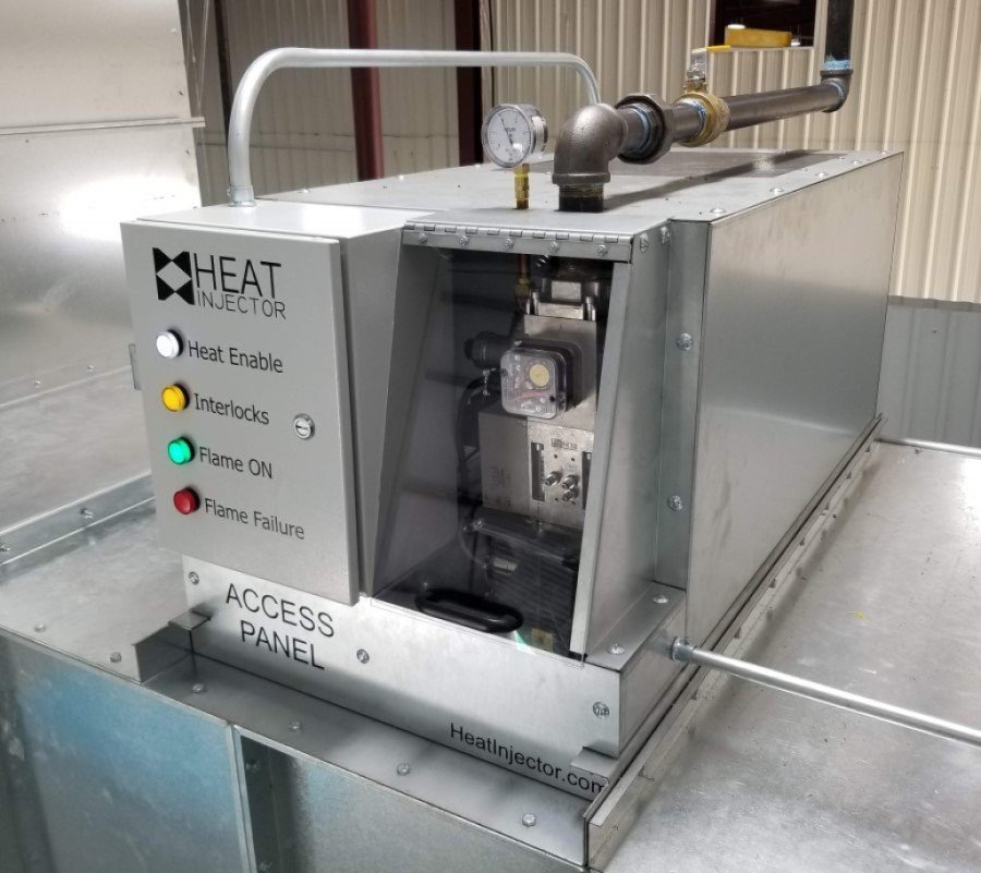
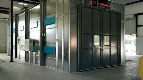
The Heat Injector service team installed a 1.5 million BTU Heat Injector on a 40 ft × 16 ft large-equipment spray booth from Global Finishing Solutions. The booth is used to paint JLG equipment that works on construction sites throughout the country.
A few modifications let the Heat Injector sit on the booth’s fresh air supply. The supply end was reinforced with support beams to carry the 42″ fan and motor, the Heat Injector duct heater, and supply ductwork that doubles as the heater’s injection chamber. Rails span from beam to beam to support the ductwork and the Heat Injector.
Why it works on a VFD-driven fan
Because of its patented dedicated combustion blower, the Heat Injector can be installed upstream of a fan controlled by a VFD. It is enabled by an intake temperature and controls the heated output at any fan speed — without dampers or motorized profile plates — while adding very little static to the airflow and supplying 1,500,000 BTU of clean, controlled heat.

How it runs
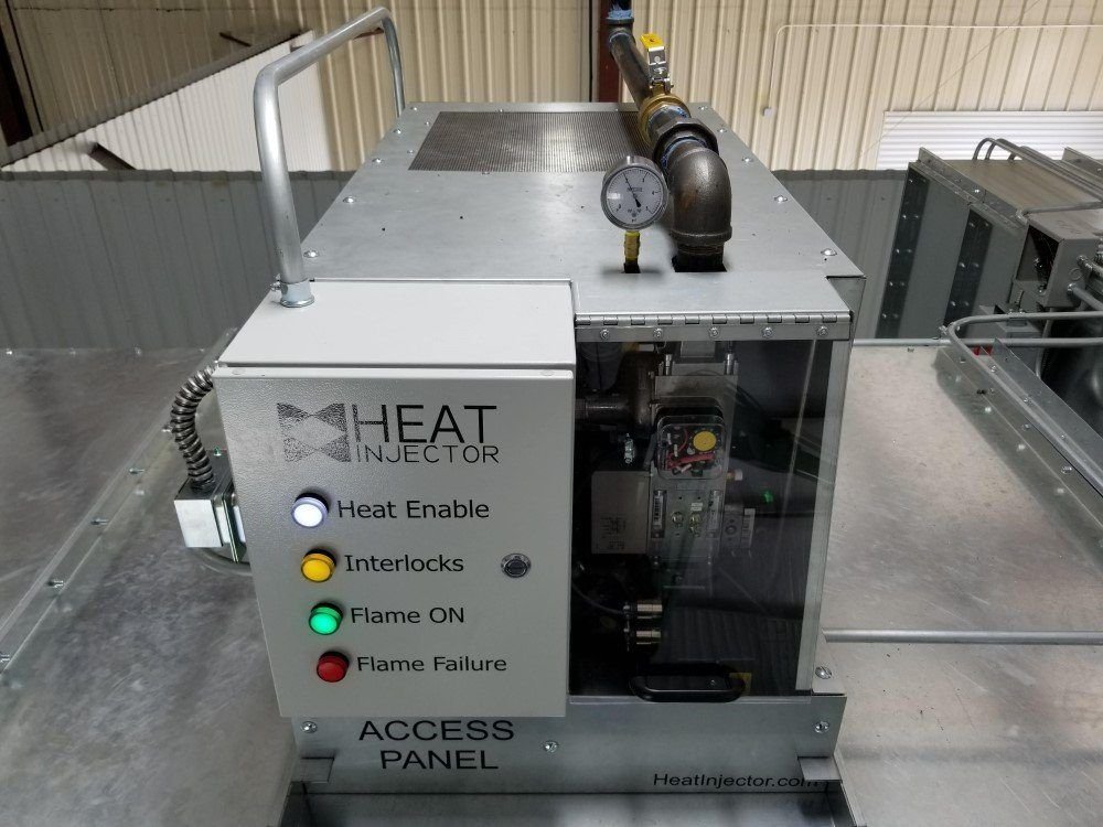
The booth control panel holds the Heat Injector controls, the system airflow controls and the booth light switch; a 480 V main disconnect feeds the supply and exhaust VFDs. When the outside air drops below the setpoint on the intake temperature controller, the call for heat is enabled and the Heat Injector lights either its green flame-on light or its red flame-failure light. Once the flame is on, the Heat Injector PID-controls the heater to the desired discharge temperature — about 75°F here. The same system could produce +140°F if drying is needed.
Safety interlocks
- Upstream and downstream high-temperature limits, both manual reset
- Low gas pressure switch on the inlet, and high gas pressure switch on the regulated side to confirm the regulator is working normally
- Redundant gas valves with a visual indicator and proof of closure (POC) on the gas train
- The system will not ignite unless the low fire position switch is made, and will not stay running unless the flame rod senses flame
All of these flame safeties are automatic once the heat enable is sent to the Heat Injector.
Videos

Planning a booth or make-up air upgrade?
Tell us about your airflow and temperature targets.